Saturday, May 19, 2012

Binding

The guitar with binding is pictured at left.  I mentioned that I wasn't happy with the way the binding went on my guitar, so perhaps a word or two of explanation.   I put it on in the standard way -- that is, I bent it to the shape of the guitar, and glued it in place using painter's tape as a clamping mechanism.   The channel cutter did a perfectly fine job of cutting the channel at a consistent depth around the guitar.  It's depth was shy of the thickness of the binding material (maple) or the binding material was proud of the guitar, and you can see the shavings where I scraped it down to be flush with the sides, soundboard, and back of the guitar.  All that works pretty much as advertised with a couple of exceptions.

Let me talk about the intersection of the back and the tail block.   Looking at it straight on, I think I did a reasonably good job of getting the two pieces of binding material to come together in a tight seam.  That too I did in the standard way.  I glued one piece of binding in place, then trimmed it back to the center of tail block inlay using a razor saw (cut at an angle) then a chisel.  The second piece of binding was glued in place up to the first, and I cut it away with the razor saw, then tweaked its fit carefully with a file.  I did the same on the soundboard side.  As I say, I am relatively happy with the way it came together.

 Looking at it from another angle, you can probably see the flaw that is annoying me.  I'm not entirely sure what I did wrong, but there was a gap that showed up between the back stripe and the binding.  I had cut the purfling channel not quite up to the back stripe, and then cut the binding channel.  I cleaned up the purfling channel to the back stripe with a chisel, and then glued the purfling in place.  I did the miters with an xacto knife.  The purfling was, or so I thought, flush with the binding channel, but when I removed the tape and scraped it flush with the back, there was a gap.  I filled it with epoxy and maple dust, but it is still visible.  Not completely happy with that.

There was another issue with the binding around the guitar.  I cut it too thick, and so I had difficulty getting it to set properly in the binding channel, and the tape didn't provide enough clamping pressure to keep it tight against the channel while I was doing the fitting.  Here again, I got a couple of gaps around the periphery of the guitar.  Again, I filled them epoxy and dust, but I can still see the gaps.  Not completely happy with that either.

My solution goes something like this.  Patience is a virtue, and one that I sometimes lack, but first, since I am cutting the channels with a rabbet bit and bearings, I should cut the channels for the purfling and the binding on the guitar body.  I can then use the channel itself to cut and finish the binding material to thickness.  I would still want it slightly proud of the channel to be scraped flush, but it would be considerably thinner, and the spring back after bending more amenable to adjustment with the tape's clamping pressure.

Sunday, May 13, 2012

Been Some Time

It's been some time since my last post, but life in Academe heats up over the latter part of April, first part of May -- all the celebrations leading to graduation.   I did fit the back and soundboard of the guitar, and glued it up.  You can see it in the photo at left. 

There are a couple of things I would do differently.  First, there is order of precedence.  I would glue up the back first.  It seems a well-duh! moment, but it's difficult to clean up squeeze out through the sound hole.  Second, I took the guitar out of the mold when I installed the end graft, and didn't put it back in.  I have had an idea for some time now to leave the guitar in the mold, and use violin clamps to glue up the back.  Once the shape has been determined, it can be removed from the mold to glue up the soundboard.  Third, I need to make a bevy of violin clamps.  It's possible to use various and sundry clamps, as I did, but the violin clamps would make it so much easier.

I did do some work on the binding channel.  I have pictured the binding jig in a previous post, but you can see it above, ready to use.  The guitar sits in the cradle, and the jig rides along the side as you cut the binding slot.  Some additional pictures are below to give some idea of the construction of the cradle and the jig.  Pretty simple stuff really.  The jig is essentially a drawer riding on metal full extension slides, which allows for up and down movement.  The hole at the top of the drawer is the "grip" for setting it down on the guitar.  NOTE:  do this carefully, particularly, on the soundboard.  Don't want to mar good work.

The router is attached to a plexiglass base that is inserted in the slot that you can see in the drawer toward the bottom.  It fits snugly for the moment, so I didn't put in a planned locking mechanism, but it would just be a set screw through a hardwood block above or below the slot.

In the photo at left, you can see the plexiglass base.  It is shaped to avoid touching the guitar except at very specific locations on the top and sides.  I use a rabbet bit, with a set of replaceable bearings.  There are other ways to do it, but I had the bit, so might as well use it.  I can get pretty close to the right depth, and I always make the binding a bit proud regardless, then scrape it down to final thickness after I've glued it up to the guitar.

The cradle is pretty straight forward as well.  It's just cut to the shape of the guitar, with the rests that you can see pictured below.

 As I said, I've cut the binding slots, and I did it by setting the guitar in the cradle, leveling it, and then running it around the edges of the guitar.  I'll talk a bit more about installing the purfling and binding in the next post, but I am running into some difficulties.


Monday, April 9, 2012

Finished Cradle

As promised, here are some photos of the finished cradle.   On the order of things I would do differently, if I had it all to do over again, I would extend the center of the basket to accommodate the hanger.  I am not happy with the mechanism that I made up.  It adds an element of fussiness to the design that wasn't necessary.  I'm finishing it with Tung Oil.  The cherry will darken over time, but in the meantime, it is au naturel in color.  It now awaits my grandson. 


Sunday, April 8, 2012

Cradle Progress

I have made some additional progress on the cradle.  I have assembled the stand.  The feet are a lamination of two pieces of Cherry.  The vertical piece is attached to the feet with a through mortise.  I cut the the mortise for the vertical piece prior to gluing it up, which simplified matters enormously.   The stretcher is actually a lamination as well.  I did not have a piece of sufficient width to run the required length, so I glued up two narrow pieces with a strip of walnut between.  When I cut the decorative channel in the stretcher, I centered it on the walnut.  If I had it to do over again, I might not cut the channel, but once cut, always cut.


The stretcher is also a through mortise.  That I cut on the drill press with a 3/8th inch forstner bit, and cleaned it up with a chisel.  You can see in the photo that it needs to be sanded flush, and cleaned up as well  The two narrow pieces that I glued up for the stretcher were not the same width, so the walnut strip was not centered in the piece, but when I cut the tenon, I centered the walnut strip in the mortise.  The walnut dowel pins are not necessary.  The through mortise would have given more than enough strength for that joint, and so the pins are purely decorative.


The hanging assembly for the basket will fit in the half circle on the vertical piece (the head stock).  You can see it in the photo below.  The "hangers" will be cut from walnut scrap, and will be pinned in place with dowels, that will complement the dowel pins on the feet.  I need to finish shaping the hangers, but they are a variant of "Molly's Cradle," the plans for which can be found with a quick web search.  Personally, I like my idea better, but others may have a different opinion.


I hope to finish it today, and will post details on the "hangers" when I have them all together and cleaned up.


Sunday, April 1, 2012

Progress on Cradle

I made a bit more progress on the cradle.  I finished the slats on the other side and laminated the feet and rough shaped them. 


I have partially shaped the spindles that will suspend the cradle, but I haven't quite decided yet what I want to do with them.  You can see in the photo above, the through mortise that will will hold the rail.  I'm going to laminate the rail from the cherry and some walnut.  I also bought a walnut dowel to do the pinning, so the walnut should offset the cherry.  It won't be as obvious as the cherry ages, but it will look sharp initially. 


For reasons that ought to be obvious, I want the head of the spindle to look a bit like the headstock of a guitar.  I am thinking of putting dowel pins along the "headstock" to suggest tuning pegs, but we'll see.  It might be altogether too cute.  At any rate, hope to finish it next weekend.


Monday, March 26, 2012

Cradle

As promised, here is a photo of the cradle in progress that I promised for my new grandchild.  I decided to make it from Cherry.  I still haven't decided how I want to finish it.  I would like to leave it alone.  There is plenty of sun shine in LA where it will find its eventual home so it will darken with age naturally and that appeals to me, but since I'm making for my son and his wife, I should probably ask them. 

As I mentioned the design is fairly simple.  I wiped it with mineral spirits so you can see the through mortise and tenon joinery that attaches the rails to the end pieces.  (Disregard the plane marks.  I will sand them away, then finish it off it a card scraper for the sheen.)  I cut the mortises on the drill press with a 3/8 inch forstner bit, and cleaned them up with a chisel.  As you can see, I did not square the ends of the mortises, but rather rounded the ends of the tenons.  That's more an aesthetic decision.  I like the rounded ends.

 I glued up the end pieces with the rails before installing the slats.  I stood and stared at it for some time, then tried it with a dry fit, and it worked fine.    The rails have a 1/4 inch groove cut along the length of the that hold the slats.  The slats themselves were cut from scraps left from the rails and the end pieces.  They should be slightly proud of the 1/4 inch, so one can plane away the saw marks, and adjust for a snug fit (though not too snug or they are difficult to fit into the groove).  I put all the slats in place, then starting in the middle, I put 1 inch spacers between each slap, except at the ends, where a bit of adjustment on the length of the spacer was needed.  The spacers between the slats stand about 1/8 inch proud of the groove, so they add a shadow line.  The spacers themselves are glued in place, with a generous bead of glue along the bottom of each one.  Since the slats are not structural, the hidden squeeze out from the spacers is enough to hold the slats in place.   I will finish the other side with off cuts from the stand.   

Saturday, March 24, 2012

Kerfing & Cradle

I have made some progress on the guitar, but not as much as I would hope.  I traveled to Denver last week end to attend to family business, but I have installed the kerfing.  My jig for making the kerfing is multi-purpose -- basically my cross cut sled for my table saw.

The saw sled has an auxiliary fence clamped to it with a brad nail driven into the bottom.  You can see that the brad is about 1/4 inch from the saw kerf, and the depth of cut is set just shy of the 1/4 inch thickness of the kerfing strips.  I cut the strips on my band saw (now working!) and run a plane over them to remove the saw marks.  One set of two strips, for the back, is cut from walnut, the other set is cut from redwood, for the soundboard.  For the first cut, I push the strip up against the brad, make the cut, adjust the depth and cut and run it over the blade again if necessary, then set the kerf over the brad, make the second cut, and so on.  It's tedious, but it works.

When I've cut the strip, I run a plane over the back until it is paper thin, then do a test fit, cut it to length, and glue it into place with a whole bunch of spring clamps.  When I glue it in place, I leave it slightly proud of the side, and level it down after the glue has dried.  It looks like this when its finished.  I'll do some additional leveling when I'm ready to install the back and sound board. 


In the meantime, I have started on another project.  My youngest son has commissioned me to make a cradle for my newest grandchild due in April.  I've opted for a rather simple design, so I will let it emerge as I go along.  Today, I succeeded in purchasing the wood (cherry) and gluing up the end pieces. 

While the glue was drying, I cut the four rails for the sides, and the slats that will go into one of the sides.  I have a trick for installing the slats.  I cut a 1/4 inch slot with my dado blade along the length of the rails.  The slats are set apart by spacers in the slot, so they are perfectly spaced, the spacers provide an attractive shadow line, and so all is good.  Unfortunately, I came up a little short on the amount of wood I bought today, so I only have enough for one set of slats, for one side, but you can see rail design, and the slats.  I hope to finish the ends, and one side tomorrow, so I'll have more pictures.


Sunday, March 11, 2012

Side Bending

I have thicknessed and bent the sides for my guitar.  There really is no way of describing the bending process in words.  A person just has to do it to discover that it's not that difficult.  The tools I use for bending are pictured at left.   

The first step, however, is to mark the sides.  I put them side by side, as a book-marked pair, and marked the waist bend on both.  Do it with something that won't wash away as you soak the sides.  Because I begin with the waist, and I would encourage people to do that, if it's marked you will avoid bending two left sides and the two ends will align with grain patterns.

The stainless tray was fashioned for me by students at the college, and it has come in very handy because it is side sized.  I soak the sides to be bent in hot water and a cap full of Downy for about an hour or so before bending.   The Downy, or any fabric softner, does just that, it softens the fibers so they bend more easily.   The bending iron was a gift from my kids.  I had an elaborate pipe and blowtorch set up before, but I would encourage purchasing the bending iron.  I clamp it in my bench clamp, and let it heat up as the sides are soaking.  When all is ready, then just bend.  I wrap the bend in a wet cloth, press it against the iron, rocking it slightly, until I feel the fibers loosen and the bend taking shape.  I use the clamping jig as a template, and when it is right, I clamp it into place to cool and set.   I don't worry about a bit of spring back if the side can be clamped into the mold without excessive forcing.   I then clamp it in the mold, and mark the centerline to cut off any excess from each end of the side. 

You can see the sides in the mold in the photos to the left and right.  Before gluing up the sides, one needs to fashion the head and tail blocks.  The tail block is made from bass wood.  Other woods could be used, but I like bass wood, in part because it does not have a resonant overtone, and in part because it is light in weight.  The head block is made from mahogony.  Usually, I would use some left overs from the neck, glued up into a block of the right size, but this particular block I purchased from LMI.   You can see the mortise for the neck tenon in the photo below.  I cut it in multiple passes on the router table with a 3/4 inch straight bit.  I will cut away the excess side material later clear the mortise.

When I glue up the sides, I have the soundboard side flush with the top of the head and tail blocks.  That keeps everything at the right angles, no pun intended.   When the glue has dried, the next step is to arch the back.  In the photo below, you can see the preliminary arch.  I usually divide the guitar in half along the center line, and then plane along the side with my block plane, along each side, starting with short strokes near the block, then taking longer and longer strokes, until the side is planed flush with the block.  When I have glued in the kerfing, I will take away some of the peak as I level the kerfing. 


Sunday, March 4, 2012

Band Saw & Back Bracing

I'm thrilled.  The parts came in for my band saw, so I was able to assemble it yesterday.  Everything worked, and so despite being under six feet of water and sitting for several months in a storage shed, it's almost as good as new.  At the instant, I don't have blades for it, but the end is in sight!

If I seem overly expressive, for lutherie work, the biggest and the best band saw you can buy is worth the investment.  Why big?  The impulse is to buy a smaller band saw -- a guitar sized band saw -- but that is a mistake.  Because smaller band saws won't cut the plates for the back and sound board on a guitar.  You need a saw with at least a 10 inch depth of cut, and able to accept a 3/4 inch blade -- at least.  Although I love LMI, and I am always pleased with the quality of their products and their service, it's cheaper and more satisfying to start from scratch on all parts of the guitar.

Beyond that, I have done some work on the back of the guitar.  There is an order of precedence to the back.  One begins, of course, by bringing the bookmarked plates to thickness.  I aim for a thickness between 3/32 or 1/8th inch.  I joint the two plates.  If there is no back strip, that is sufficient, but if there is a backstrip, I like to cut it at the same thickness as the back and glue it up.   You can see it in the photo at right.

The strip itself is maple, and I ran a strip of B/W purfling along either side, just to set it off a bit.  Because it is laminated, and not inlayed, it runs through the entire thickness of the back.  A word of caution, this makes for a more fragile joint, so you will want to handle it carefully, until the reinforcement strip is glued in place.

The next step is the reinforcement strip.  The best way to get the correct grain orientation is to cut a 1 inch wide strip off the bottom of the glued up soundboard.  I used a piece of the redwood scrap, and cut mine from that.  Because I didn't have my bandsaw, I had to cut it on the table saw and so it was cut thick.
   

Once I had glued it in place, I simply planed it down to a better thickness -- again about 1/8 inch.  I glued it in place on the Go-Bar deck, using every go bar I could muster along its length.  You can see the reinforcement strip in the photo at left.  When I had the reinforcement strip in place, I traced the outline of the guitar on it the back, then cut out the rough outline using my jig saw.  Normally I would use my band saw ... see what I mean. 

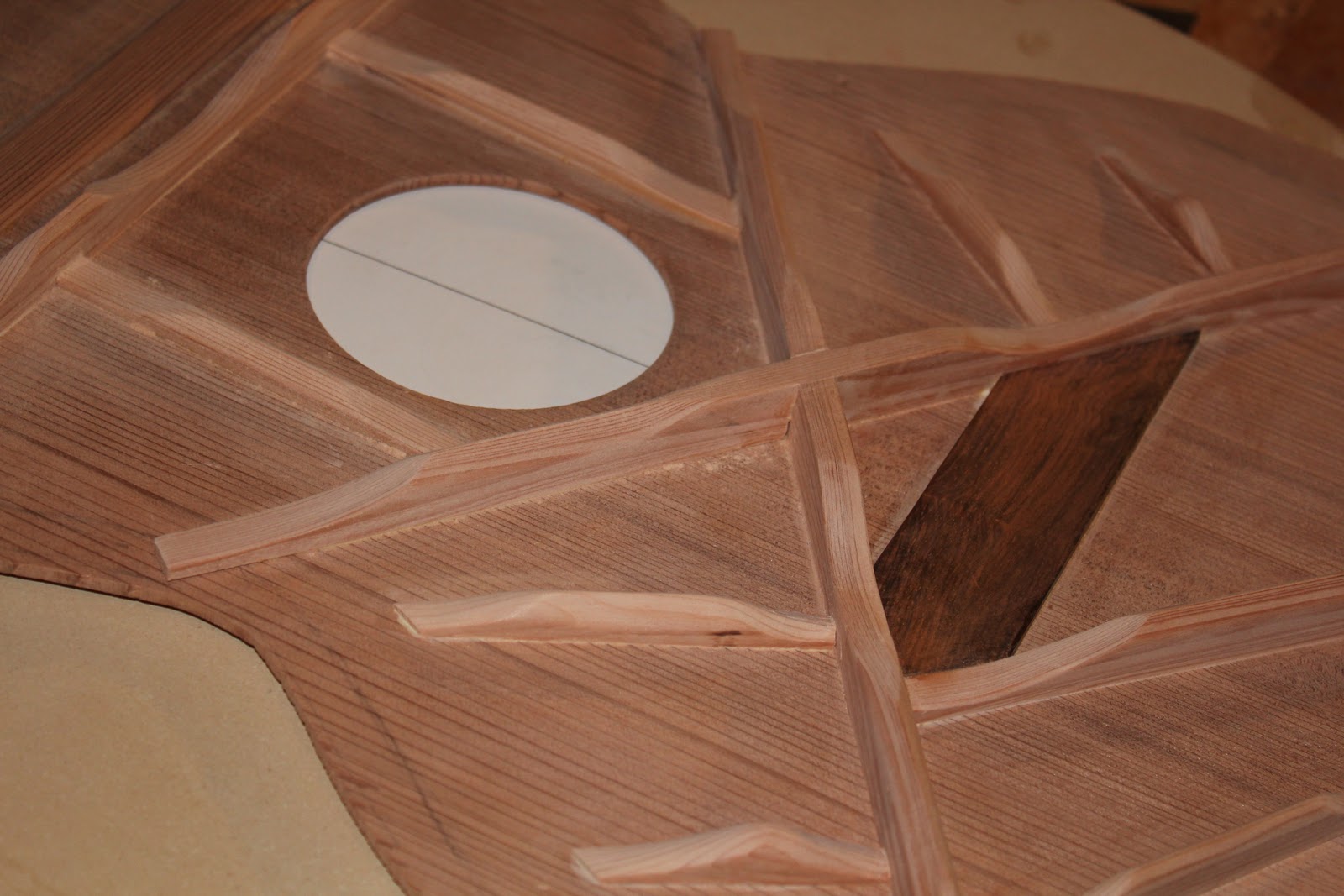
The next step is the bracing.  I used redwood for the bracing of the back.  I had originally thought I would use the black walnut, but decided against it.  I wanted a lighter bracing, and the redwood seemed to be the right path.

One does the bracing for the back in the same way that one does the bracing for the soundboard.  I used a block plane to cut the rough radius on the bottom of the brace, then sandpaper on the radius dish to finish an exact fit.

I laid out the locations of the braces along the reinforcement strip, and cut through the reinforcement strip with my small X-Acto razor saw at a right angle to reinforcement strip.  Then covering the kerf with the brace, I would mark the thickness of the brace on the reinforcement strip with a sharp X-Acto knife, then cut the second kerf.  I popped out the reinforcement strip with a chisel.   I then glued the braces into the slots on the reinforcement strip.

The top two braces are 3/8th thick by 3/4 inches high, the bottom two braces are 7/16th inches thick and 1/2 inches high.   

When the glue had set, I then carved the braces.  I measured in two and a half inches from the inside edge of the guitar, marked the brace, and cut the scallop using a sharp chisel.  When the scallop was done, I cut the top edge to a peak using my mini-plane.  The final step will be the finish sanding. 


Sunday, February 26, 2012

Back & Binding Jig

Last Sunday, I had some time, and the scrap left from my molds, so I began my binding jig.  The construction is less complex than it looks.  I began with the plastic that would serve as the router mount, and cut it to size.  In the picture, the router is mounted backward, and I still have some work to do on the mounting plate, but it's width is correct and that was the crucial dimension.

Next, work on the interior box.  On the material for the interior box (3/4 MDF) I cut the groove for the mounting plate on the table saw with a dado blade.  It took a bit of fussing with shims to get the width of the groove correct, but I wanted a tight fit.  Next, I cut the sides to width, about 2 1/2 inches, and length.  The drawer glides determined the length.  With the mounting plate in the side grooves, used that to get the measure for the width of the back.  I used a simple butt joint, then glue and brads to build the box.  You can use the mounting plate to keep things aligned.

The next step was the exterior box.  Again, I cut the sides to width, about 2 1/2 inches.  Again, the interior box and the drawer glides determined the height.  It is set so the router, at the lowest level, will not bottom out its bit.   A word on the base.     You can see in the photo above and to the left, that it is flush with the front, but extends back.  When the jig is in use, I plan to clamp it behind to one edge of my bench, and you can see from the photo that it supports the weight of my router without the clamps.

I built the exterior box in the same way.  The width of back was determined by the interior box, with the drawer glides.  I then used a simple butt joint with brads and glue.  I cut and installed the base last.  When the glue had dried, and I'd rounded over all the edges, I installed the drawer glides.  Make sure you get the orientation right, but basically the interior box slides up and down like a drawer in and out.

Next, I need to fuss a bit with the router mount, and build the guitar cradle, but on the whole, this project went together better than I would have anticipated.


I had ordered the back and side plates from LMI.  I was side tracked a bit.  Originally, I had intended to use mahogany, but got side tracked by the idea of black walnut, a domestic wood.  It arrived on Wednesday, so I was able to get a start on the back of the guitar.

I brought the thickness down some with my toothing plane, and my thickness sander.  With the toothing plane, I only worked the interior surface.  It's quicker than the thickness sander alone.  There was a bit of tear out, but the thickness sander removed it along with the toothing plane tracks.  

The center stripe is maple from the local hardwood store, with black/white perfling on either side.  The stripe, as you can see from the back view goes all the way through, and is not an inlay.  I prefer this to an inlay, particularly since the joint is reinforced.  The assembly needs a little fussing to get it all lined up in the lattice jig, but then I don't need to worry about sanding through the inlay.  I used scraps from the soundboard redwood to make the reinforcement strip.  Once I had glued it in place on the on the go-bar deck (using every go-bar I had to insure even pressure along the length) I planed it level, then planed a slight bevel on either side, which is rounded over when I sand it.  Today, I will work on the bracing for the back, which I intend to make from walnut, also purchased from the local hardwood store. 

Monday, February 20, 2012

A Bit More Progress

Another bad weather day -- about a foot of snow, but I was able to make a bit more progress.   In the photo at left, you can see the bending mold, now on a stand with the clamps installed.  I made them from scrap oak, but just about any wood will do.  The clamp at the waist has been contoured on the bottom to fit the waist snugly.  I did this on the bench sander, just rocking it back and forth, and checking it against the mold until it was about right.  Although it is not visible, the far post passes through a slot, not simply a hole.  When I had drilled the holes for the posts, I simply cut down with a gents saw into the hole.   This allows one to position it more quickly, a necessity if you are using the Sloan method of bending -- essentially boiling the sides until they are pliable, and clamping them into a bending mold like the above.  I have cracked several sides attempting it, and wouldn't recommend it, but then again Sloan has built more guitars than I will likely ever build. 

In the photo at right, you can see the completed mold.  I decided against the strap clamp for a couple of reasons.  First, they were too stretchy.  As I would tighten the extenders, it opened up the mold.  Second, the arrangement visible in the photos gave the mold greater stiffness.  Basically, it is simply a piece of 1/2 birch ply, tacked and glued on one side, bolted on the other with a 3/8th inch bolt.  Perhaps not the most aesthetically pleasing arrangement, but it works like a champ.

You can see the extenders below.  It is a simple arrangement as well, and a number of luthiers use something similar.  Essentially, it is a 3/8th by 16 threaded rod inserted into a 1/2 steel tube.  Both are available at the local hardware store.  At either end, the rod and the tube are epoxied into the blocks.  When the wing nut is tightened against the steel tube, it extends and puts pressure against the side in the mold. 


To make them, I laminated three scraps of 3/4 MDF, and from that cut six blocks to size.  Using the mold, I marked the contour on each block, and again shaped them on the bench sander to match the contour of the mold.  I then drilled the 3/8 inch hole on one side, the 1/2 inch hole on the other, about 2/3 of the way through the block. 

I then epoxied the steel rod into the 1/2 hole, and cut it off at about the center line of the mold, or where the two halves of the mold come together.  Since the holes were not precisely to the same depth, this worked well, and kept a sense of symmetry.
For the threaded rods, I did the same.  I epoxied one end into the block, then marked it at about one inch in from the opposite block.  In other words, the rod extends into the tube to about one inch in from the tube-side block.  This allows for enough rod in the tube to keep it straight, but also enough in and out play to remove the extenders when the kerfing has been installed on the side. 

The contoured end of the blocks were covered with cork.  The inside contour of the mold was also covered with cork.  It not only makes it all prettier, but smooths out some of the differences between the three layers of the mold and provides a protective cushion.  It's probably not necessary, but I do it regardless.  The cork comes in a roll and can be purchased in places like hobby lobby.  I cut the strips over-sized by about 1/4 inch.  Although the cork came with an adhesive, I still sprayed the interior of the mold with contact cement, waited for that to dry, and installed it carefully.  I then trimmed the excess away with a sharp exacto knife, and rounded it over with a file.        

Sunday, February 12, 2012

A Wee Bit of Progress


Yesterday, I spent on yet another household project.  My wife does not like the arrangement of the living room, so I spent the day hanging a cabinet and the TV from the wall to free up floor space.   the challenge was not so much the hanging as the hiding of all the cords that support the electronics.  I have to admit, it looks much better, and she seems pleased, which is good enough for me. 

Today, however, is not a good weather day, so I couldn't move the vehicle out of the garage into the drive so I could get access to most of my tools, particularly the table saw.   I did make a bit of progress over last week on the bending jig.  In the picture above, you can see the hardware set for the upper bout and waist clamps, and the picture below, you see the hardware set used for the lower bout hold clamps, and in the last picture, the half-finished jig.  The stand is a piece of black pipe with two flanges.  The lower flange will be attached to a base.   I needed access my table saw in order to make the base.  


The upper and lower bout clamps are spring loaded, the waist clamp is shaped to fit the waist and is brought down with the two wing nuts.  As I said, I bend the sides first, freehand, then put them in the jig to rest, so speed isn't particularly crucial.  I do like to let the sides rest over-night, particularly if they are still wet from the bending process.

Next week-end, I hope I will have access to my table saw, and I will make the base, the clamps for the bending jig, and the spreaders to complete the mold.  More details to follow.

Sunday, February 5, 2012

The Assembly and Bending Molds

I had a little more time to work this weekend, because my wife is out of town with the kids and grand-daughter.  She was a finalist in her school spelling bee, and grandma had to see it.  I'm a bit disappointed that I didn't get to see it, but we have an aged dog that doesn't travel well, so I am dog-sitting.  At any rate, the soundboard is as complete as I can make it for the moment, and I  don't have the plates for the plates for the sides and back.   So, wife away and at am impasse on the guitar itself, I decided to make the molds.  Since it involves MDF, it's also a hellacious messy, dusty job, something my wife fusses over the whole time.  What she doesn't see won't bother her, so long as I clean up well before she returns, all will be golden.  SAFETY NOTE:  wear a respirator. 

To be honest, I forgot to take pictures when I made the primary pieces of the mold, but the idea is fairly simple.  I used my router, a 1/4 upcut bit, and a brass bearing.  I took my initial template, clamped it first to a piece of 1/4 MDF on top of a piece of 3/4 MDF.  I clamped it my bench, tightly -- that's important, tightly -- and cut around the perimeter of the template.  I set the depth so it cut through the 1/4 inch MDF on the first cut, then another 1/4 inch into the MDF below.   Since there is a slight off set between the brass bearing and the initial template, the 1/4 MDF becomes the new template.  I set it aside, and cut around the template five more times, just 1/4 inch into the 3/4 MDF.

A couple of notes of caution.  When you cut left to right following the template, the router has a tendency to drift away from the template on the right side of the cut -- in the picture above, on the lower bout side.  Position yourself so you can keep good pressure between the brass bearing and the template.   

On the 3/4 MDF with the guitar shaped groove, I used my jig saw and cut along the groove, being careful not to cut outside the groove.   You should have twelve pieces, six for the outside perimeter of the guitar, six for the inside perimeter of the guitar.   Each of the six pieces should have a smooth contour left by the router bit, and a rough contour left by the jig saw.  I used my pattern bit, mounted in my router table, to trim off the excess left by the jig saw, running the bearing against the smooth contour, the blade against the rough contour.  I glued them up three at a time, trimmed the edges to make everything neat, and installed the dowels. 

Another couple of notes of caution.  My initial template extends a couple of inches beyond the center line.  Mark the center line.  When trimming the ends where the two halves of the mold come together, you want to hit the center-line mark precisely so the two halves of the mold come together symmetrically.  The dowels are there to keep things aligned and to keep the mold from folding up like a book when the band clamp is tightened around it.  There are a variety of ways that one can bind the two halves together, but after considerable experimentation in the past, this works well.  I have the band clamp.  It provides sufficient resistance for the extenders that hold the guitar against the mold.    So there you have it, an assembly mold.  Next weekend, I'll make the extenders. 

I did get a start on the bending mold.  I'll explain it in more detail, but you can see that it is basically the pieces that are cut out of the center of the mold.  You can see where I've drilled for the hardware.  Since it is six sheets of 3/4 MDF thick, I don't have a drill bit that will penetrate that far, so I carefully clamped two together, and drilled through them.  I glued up the bending mold, three sheets at a time, first using one drilled piece, then the other drilled piece.   Next week end, along the with extenders, I'll install the hardware and make the various hold down for the bending mold.  By the by, I do not actually use this for bending, though if one had a heat blanket, one could.  I bend freehand, but clamp it into the mold to finish drying and to rest.  It's also useful for holding bent binding while it's waiting for installation. 

Sunday, January 29, 2012

Fully Braced Sound Board

Here you can see the fully braced sound board, with all the scallops cut.  I still haven't received the parts for my band-saw, so I will likely put off the back until I get the parts, and then again, maybe not.  My wife promised that we could go in search of wood stores on Saturday next -- as she put it, not my favorite thing to do -- and if I can find a suitable piece of mahogany, I will resaw it again at the school.

To tap tune it, I hold it by spreading my fingers in the sound hole, then rap it with my knuckle at the bridge plate.  I sand and scallop until I no longer hear over-tones.  None of the bracing is of a standard size, and frankly, I don't think it's that terribly important.  If you look at several guitars, they are all braced differently, and they all swear by the pattern and dimensions of their bracing.  If you are going for a certain tone (e.g. vintage Martin) I would copy the dimensions, but I am still finding my tone, and I don't mind producing something slightly unusual.


For those who care, however, the x-bracing is 3/8th wide by 1/2 inch high.  The upper traverse brace (above the sound hole) is likewise 3/8th wide by 1/2 inch high.  The lower bout bracing is 1/4 wide by 1/2 inch high.  The finger bracing is 1/4 wide by 3/8 inch high.  It's a little heavier than you might find on most guitars, but tap tells me I'm not sacrificing much in the way of response and I want the redwood to be braced a bit heavier than spruce.  It's stiff enough, but not as stiff as the spruce, and I don't want it bulging under the pressure of the strings.