Sunday, February 26, 2012

Back & Binding Jig

Last Sunday, I had some time, and the scrap left from my molds, so I began my binding jig.  The construction is less complex than it looks.  I began with the plastic that would serve as the router mount, and cut it to size.  In the picture, the router is mounted backward, and I still have some work to do on the mounting plate, but it's width is correct and that was the crucial dimension.

Next, work on the interior box.  On the material for the interior box (3/4 MDF) I cut the groove for the mounting plate on the table saw with a dado blade.  It took a bit of fussing with shims to get the width of the groove correct, but I wanted a tight fit.  Next, I cut the sides to width, about 2 1/2 inches, and length.  The drawer glides determined the length.  With the mounting plate in the side grooves, used that to get the measure for the width of the back.  I used a simple butt joint, then glue and brads to build the box.  You can use the mounting plate to keep things aligned.

The next step was the exterior box.  Again, I cut the sides to width, about 2 1/2 inches.  Again, the interior box and the drawer glides determined the height.  It is set so the router, at the lowest level, will not bottom out its bit.   A word on the base.     You can see in the photo above and to the left, that it is flush with the front, but extends back.  When the jig is in use, I plan to clamp it behind to one edge of my bench, and you can see from the photo that it supports the weight of my router without the clamps.

I built the exterior box in the same way.  The width of back was determined by the interior box, with the drawer glides.  I then used a simple butt joint with brads and glue.  I cut and installed the base last.  When the glue had dried, and I'd rounded over all the edges, I installed the drawer glides.  Make sure you get the orientation right, but basically the interior box slides up and down like a drawer in and out.

Next, I need to fuss a bit with the router mount, and build the guitar cradle, but on the whole, this project went together better than I would have anticipated.


I had ordered the back and side plates from LMI.  I was side tracked a bit.  Originally, I had intended to use mahogany, but got side tracked by the idea of black walnut, a domestic wood.  It arrived on Wednesday, so I was able to get a start on the back of the guitar.

I brought the thickness down some with my toothing plane, and my thickness sander.  With the toothing plane, I only worked the interior surface.  It's quicker than the thickness sander alone.  There was a bit of tear out, but the thickness sander removed it along with the toothing plane tracks.  

The center stripe is maple from the local hardwood store, with black/white perfling on either side.  The stripe, as you can see from the back view goes all the way through, and is not an inlay.  I prefer this to an inlay, particularly since the joint is reinforced.  The assembly needs a little fussing to get it all lined up in the lattice jig, but then I don't need to worry about sanding through the inlay.  I used scraps from the soundboard redwood to make the reinforcement strip.  Once I had glued it in place on the on the go-bar deck (using every go-bar I had to insure even pressure along the length) I planed it level, then planed a slight bevel on either side, which is rounded over when I sand it.  Today, I will work on the bracing for the back, which I intend to make from walnut, also purchased from the local hardwood store. 

Monday, February 20, 2012

A Bit More Progress

Another bad weather day -- about a foot of snow, but I was able to make a bit more progress.   In the photo at left, you can see the bending mold, now on a stand with the clamps installed.  I made them from scrap oak, but just about any wood will do.  The clamp at the waist has been contoured on the bottom to fit the waist snugly.  I did this on the bench sander, just rocking it back and forth, and checking it against the mold until it was about right.  Although it is not visible, the far post passes through a slot, not simply a hole.  When I had drilled the holes for the posts, I simply cut down with a gents saw into the hole.   This allows one to position it more quickly, a necessity if you are using the Sloan method of bending -- essentially boiling the sides until they are pliable, and clamping them into a bending mold like the above.  I have cracked several sides attempting it, and wouldn't recommend it, but then again Sloan has built more guitars than I will likely ever build. 

In the photo at right, you can see the completed mold.  I decided against the strap clamp for a couple of reasons.  First, they were too stretchy.  As I would tighten the extenders, it opened up the mold.  Second, the arrangement visible in the photos gave the mold greater stiffness.  Basically, it is simply a piece of 1/2 birch ply, tacked and glued on one side, bolted on the other with a 3/8th inch bolt.  Perhaps not the most aesthetically pleasing arrangement, but it works like a champ.

You can see the extenders below.  It is a simple arrangement as well, and a number of luthiers use something similar.  Essentially, it is a 3/8th by 16 threaded rod inserted into a 1/2 steel tube.  Both are available at the local hardware store.  At either end, the rod and the tube are epoxied into the blocks.  When the wing nut is tightened against the steel tube, it extends and puts pressure against the side in the mold. 


To make them, I laminated three scraps of 3/4 MDF, and from that cut six blocks to size.  Using the mold, I marked the contour on each block, and again shaped them on the bench sander to match the contour of the mold.  I then drilled the 3/8 inch hole on one side, the 1/2 inch hole on the other, about 2/3 of the way through the block. 

I then epoxied the steel rod into the 1/2 hole, and cut it off at about the center line of the mold, or where the two halves of the mold come together.  Since the holes were not precisely to the same depth, this worked well, and kept a sense of symmetry.
For the threaded rods, I did the same.  I epoxied one end into the block, then marked it at about one inch in from the opposite block.  In other words, the rod extends into the tube to about one inch in from the tube-side block.  This allows for enough rod in the tube to keep it straight, but also enough in and out play to remove the extenders when the kerfing has been installed on the side. 

The contoured end of the blocks were covered with cork.  The inside contour of the mold was also covered with cork.  It not only makes it all prettier, but smooths out some of the differences between the three layers of the mold and provides a protective cushion.  It's probably not necessary, but I do it regardless.  The cork comes in a roll and can be purchased in places like hobby lobby.  I cut the strips over-sized by about 1/4 inch.  Although the cork came with an adhesive, I still sprayed the interior of the mold with contact cement, waited for that to dry, and installed it carefully.  I then trimmed the excess away with a sharp exacto knife, and rounded it over with a file.        

Sunday, February 12, 2012

A Wee Bit of Progress


Yesterday, I spent on yet another household project.  My wife does not like the arrangement of the living room, so I spent the day hanging a cabinet and the TV from the wall to free up floor space.   the challenge was not so much the hanging as the hiding of all the cords that support the electronics.  I have to admit, it looks much better, and she seems pleased, which is good enough for me. 

Today, however, is not a good weather day, so I couldn't move the vehicle out of the garage into the drive so I could get access to most of my tools, particularly the table saw.   I did make a bit of progress over last week on the bending jig.  In the picture above, you can see the hardware set for the upper bout and waist clamps, and the picture below, you see the hardware set used for the lower bout hold clamps, and in the last picture, the half-finished jig.  The stand is a piece of black pipe with two flanges.  The lower flange will be attached to a base.   I needed access my table saw in order to make the base.  


The upper and lower bout clamps are spring loaded, the waist clamp is shaped to fit the waist and is brought down with the two wing nuts.  As I said, I bend the sides first, freehand, then put them in the jig to rest, so speed isn't particularly crucial.  I do like to let the sides rest over-night, particularly if they are still wet from the bending process.

Next week-end, I hope I will have access to my table saw, and I will make the base, the clamps for the bending jig, and the spreaders to complete the mold.  More details to follow.

Sunday, February 5, 2012

The Assembly and Bending Molds

I had a little more time to work this weekend, because my wife is out of town with the kids and grand-daughter.  She was a finalist in her school spelling bee, and grandma had to see it.  I'm a bit disappointed that I didn't get to see it, but we have an aged dog that doesn't travel well, so I am dog-sitting.  At any rate, the soundboard is as complete as I can make it for the moment, and I  don't have the plates for the plates for the sides and back.   So, wife away and at am impasse on the guitar itself, I decided to make the molds.  Since it involves MDF, it's also a hellacious messy, dusty job, something my wife fusses over the whole time.  What she doesn't see won't bother her, so long as I clean up well before she returns, all will be golden.  SAFETY NOTE:  wear a respirator. 

To be honest, I forgot to take pictures when I made the primary pieces of the mold, but the idea is fairly simple.  I used my router, a 1/4 upcut bit, and a brass bearing.  I took my initial template, clamped it first to a piece of 1/4 MDF on top of a piece of 3/4 MDF.  I clamped it my bench, tightly -- that's important, tightly -- and cut around the perimeter of the template.  I set the depth so it cut through the 1/4 inch MDF on the first cut, then another 1/4 inch into the MDF below.   Since there is a slight off set between the brass bearing and the initial template, the 1/4 MDF becomes the new template.  I set it aside, and cut around the template five more times, just 1/4 inch into the 3/4 MDF.

A couple of notes of caution.  When you cut left to right following the template, the router has a tendency to drift away from the template on the right side of the cut -- in the picture above, on the lower bout side.  Position yourself so you can keep good pressure between the brass bearing and the template.   

On the 3/4 MDF with the guitar shaped groove, I used my jig saw and cut along the groove, being careful not to cut outside the groove.   You should have twelve pieces, six for the outside perimeter of the guitar, six for the inside perimeter of the guitar.   Each of the six pieces should have a smooth contour left by the router bit, and a rough contour left by the jig saw.  I used my pattern bit, mounted in my router table, to trim off the excess left by the jig saw, running the bearing against the smooth contour, the blade against the rough contour.  I glued them up three at a time, trimmed the edges to make everything neat, and installed the dowels. 

Another couple of notes of caution.  My initial template extends a couple of inches beyond the center line.  Mark the center line.  When trimming the ends where the two halves of the mold come together, you want to hit the center-line mark precisely so the two halves of the mold come together symmetrically.  The dowels are there to keep things aligned and to keep the mold from folding up like a book when the band clamp is tightened around it.  There are a variety of ways that one can bind the two halves together, but after considerable experimentation in the past, this works well.  I have the band clamp.  It provides sufficient resistance for the extenders that hold the guitar against the mold.    So there you have it, an assembly mold.  Next weekend, I'll make the extenders. 

I did get a start on the bending mold.  I'll explain it in more detail, but you can see that it is basically the pieces that are cut out of the center of the mold.  You can see where I've drilled for the hardware.  Since it is six sheets of 3/4 MDF thick, I don't have a drill bit that will penetrate that far, so I carefully clamped two together, and drilled through them.  I glued up the bending mold, three sheets at a time, first using one drilled piece, then the other drilled piece.   Next week end, along the with extenders, I'll install the hardware and make the various hold down for the bending mold.  By the by, I do not actually use this for bending, though if one had a heat blanket, one could.  I bend freehand, but clamp it into the mold to finish drying and to rest.  It's also useful for holding bent binding while it's waiting for installation. 

Sunday, January 29, 2012

Fully Braced Sound Board

Here you can see the fully braced sound board, with all the scallops cut.  I still haven't received the parts for my band-saw, so I will likely put off the back until I get the parts, and then again, maybe not.  My wife promised that we could go in search of wood stores on Saturday next -- as she put it, not my favorite thing to do -- and if I can find a suitable piece of mahogany, I will resaw it again at the school.

To tap tune it, I hold it by spreading my fingers in the sound hole, then rap it with my knuckle at the bridge plate.  I sand and scallop until I no longer hear over-tones.  None of the bracing is of a standard size, and frankly, I don't think it's that terribly important.  If you look at several guitars, they are all braced differently, and they all swear by the pattern and dimensions of their bracing.  If you are going for a certain tone (e.g. vintage Martin) I would copy the dimensions, but I am still finding my tone, and I don't mind producing something slightly unusual.


For those who care, however, the x-bracing is 3/8th wide by 1/2 inch high.  The upper traverse brace (above the sound hole) is likewise 3/8th wide by 1/2 inch high.  The lower bout bracing is 1/4 wide by 1/2 inch high.  The finger bracing is 1/4 wide by 3/8 inch high.  It's a little heavier than you might find on most guitars, but tap tells me I'm not sacrificing much in the way of response and I want the redwood to be braced a bit heavier than spruce.  It's stiff enough, but not as stiff as the spruce, and I don't want it bulging under the pressure of the strings.     


Sunday, January 22, 2012

Sound Board Bracing

You can see the finished Go-Bar deck.  It took all of a half hour to build.  I cut two pieces of 3/4 MDF slightly larger than my radius dishes, nipped the corners off, drilled holes and enlarged them slightly on the top, then bolted the top and the bottom in place.  I used 5/16 threaded rods.  I could have used larger, and they would have had less wiggle, but the 5/16 are working quite well.  I didn't cut the rods, but left them at the full 36 inches.  The extra length will allow me to raise the upper deck, if I want to use it for projects other than guitars.  (My wife wants me to make some boxes for a variety of tea bags, something well crafted that could be used on the table.) 

The go-bars themselves, I made from poplar.  I had thought about ordering some fiberglass rods from McMaster-Carr, but frankly didn't want to wait.  Poplar is a stringy, hence springy, wood, so I cut some strips at about 1/8th inch thick.  Any thicker and they're too stiff.  At any rate, they work like a champ.


I have an order of precedence in gluing on the braces, and I won't outline it here.  It begins with the X-Bracing.  I begin the process by cutting them from lumber.  I'm cutting the bracing from a redwood 2 by 4 that I rescued from the Home Depot.  The first trick is the grain.  I wanted a piece with tight, even and straight grain.  It doesn't where that grain is on the billet (I'll call it a billet from here on out) but when the brace is cut, the grain should run the length of brace.  Looking at the end grain, it should be vertical to the soundboard.

I cut my X-Braces at 3/8 wide and 3/4 inches high.  They will lose a bit of that dimension when planed and sanded, but it also makes for a stiffer top.  To radius the braces, I do two things.  First, I begin by planing a preliminary radius on the brace.  Take a cut with the plane about one inch from the end, another at an inch and a half, another at two, et cetera, until you reach the center of the brace.  Do the same for the other end, then run a squiggly (technical term) pencil line down the brace.  I finish on the radius dish, as you can see in the photo, by laying sandpaper at the approximate place where the brace would lie on the sound board.  Using light downward pressure, and short strokes, I sand until the pencil lines are gone.  When I have done that, just to be sure, I put another squiggle down the brace, and sand that off as well.  I say "light downward pressure," because you don't want to bend the brace into the radius, you want to sand it into the radius.

I join the X-Brace before I glue them in place.  Layout is important.  The first step is to find the place where bridge will be on the top.  Using the LMI ruler, I measure and mark the bridge location.  I then mark the outside string locations.  The X-Brace should allow for about 1/2 inch on either side of each e string.  You want the pins that hold the strings to pass through the bridge plate, not the bracing.  The joint itself is essentially just a half-lap joint at the angle of the X.  After I have sanded the radius into it, I lay it on the soundboard, put the other brace over it, and mark the angle, then cut it with a razor saw.  I put the other brace over the other, so it covers the razor saw kerf, mark with a sharp x-acto knife, then cut the second kerf to the same depth, about half-way through the brace.   The waste between the kerfs should pop right out with a sharp chisel.


The trick is not to cut it too wide.  Better to cut the channel too narrow and take some shavings to get it to the point where the other brace slips into it snugly.  With the other brace in the channel, I mark it with the knife, cut two kerfs just inside the markings, make the adjustments for fit, and glue them together.   You don't really need to wait for the glue to dry before gluing the brace to the top, and in fact, I didn't.

You can see the go-bar deck in its full glory in the photo at left.  Here the trick is to get the brace in place with the first bar.  With the glue on the braces (and I do use Titebond) they have a tendency to slip around.  Once it is in place, then it is simply a matter of placing the go-bars so you get a nice even line of squeeze out along the entire length of the brace with no gaps.  This shouldn't be a big problem if a proper radius was sanded into the brace.  Although you can't really see it in the photo, I do have a sheet of poster board between the soundboard and the dish.  Although it isn't a big deal right now, eventually, when it comes time to adjust the kerfing on the sides, I will cover the dish with sandpaper, and so I thought I would get in the habit of protecting the show face of the sound board right from the start.

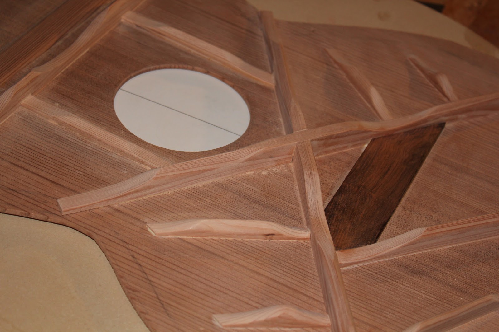
Before I glued in the bridge plate, I did scallop the X-Bracing.  The scallops on the ends of the braces start at about 1 and 1/2 inches from the sides of the guitar.  The secondary scallops are positioned so they line up with the bridge plate.

Cutting a scallop takes a little practice, but not much.  Start with the sharp chisel.  (Mine this morning were a bit dull, so I will need to attend to it.)   For the end scallops, start at about 1/2 inch back from the end.  With the back side of the chisel up, cut on either side of the brace to create a peak, then chisel then scoop the peak away.  Go back a bit on the brace, and repeat the process, cut away the sides until you have a peak, then scoop the peak away.  For the secondary scallops, at the center of the scallop, cut a kerf to the depth of the scallop.  Then do as above, just working from the center kerf to the mark.   

The next step is the bridge plate.  It is made from a block of (I think its cocobolo) that I found in the garage many years ago when we were living in Michigan. It is a beautiful piece of dense wood, and this is the first cut made into it.  I had in mind that someday, when the spirit moves me, I will make a morris style plane with the remainder of the block, but for the moment, I will let it serve as a bridge plate.  It is about 1/8th inch thick, and positioning is important.  Although I plan to make a pinless bridge, the bridge plate should be below the bridge and the pins should pass through it (not the braces!).    You can see the shaping from the photos, and the reason for the particular shape will be obvious when I install the next set of braces.  


Sunday, January 15, 2012

Rosette


I finished the rosette, almost.  There is still a little tweaking that I need to do at the joints of the wafers, but it is essentially what it will be.  The tile at the top is there primarily as reinforcement and fill.

The first step, of course, is layout.  To do this, I used my template, which has already be scribed, and traced the outline on the sound board.  I am going for a parlor-type guitar, which I interpret to mean a steel string guitar with classical like dimensions.  It also suits me because I play finger-style, and find myself switching between classical and steel strings, so some continuity in the dimensions works for me.  Consequently, I am using a 25 and 11/32nd inch scale length.  There are all sorts of ways of coming at this, but I have found that one purchase has repaid itself several times.  Get a fret rule from LMI.   Again, I am going for classical like dimensions, so I placed the 12th fret line at the top of the sound board, and marked the location of the 22nd fret on the center-line (the glue seam).  With my compass set at 1 7/8th inch diameter, I scribed the circle for the sound hole.

Once I had the tiles set out in the working scrap, which you can see beneath the rosette, the whole process became rather simple.  I set the router so it would ride within the channel that I had cut to fit the tiles, set the depth to just a whisker (about 1/64th of an inch) shy of the total depth of the tiles, double checked (actually, quadruple checked) to make sure that I would not be cutting through the soundboard at that depth, and then made the cut, testing first where it would be covered by the fretboard.  Once the initial cut had been made, I eased it out and in using the precision adjustment on my router jig to accommodate the tiles and the perfling strips.  When I was finished, I gave the rosette channel a coat of shellac to prevent bleed out from the glue.

I put all the tiles and perfling in place, leaving slight gaps at the seams so I could lift them out, one by one.  Beginning at the bottom of the rosette, I would lift out one tile, run a bead of superglue along each of the perfling strips.  I then replace and quickly position the tile between the perfling strips.  I kept going I had worked up both sides of the rosette.  I wiped away any squeeze out, and pressed the tiles into place with my fingers until the glue set.    

Before I cut out the sound hole, I did a couple of things.  First, using my template, I transferred the outline of the guitar to the back of the sound board.  That was a simple matter of using the 1/4 hole for the router pivot, and a similar hole at the center of the sound hole in my template.  When sanding the back, make sure that you never sand away the lines that they cannot be retraced.  I also leveled the rosette.  Nothing fancy there, I just used my trusty card scraper, newly sharpened, taking light passes until the rosette was level with the sound board.   I then sanded it using 120 grit sandpaper on my sanding block.  A word of advice, never sand without a sanding block.  It's amazing how quickly one can cut shallow hollows sanding without a block.  Mine is just a scrap of cherry with a cork face.  I wrap the sandpaper over it and hold it in place as I sand.

To cut out the sound hole, I swapped the 1/4 inch bit in my router to a 1/8th inch bit, made the adjustments so there would be a lip of redwood approximately 1/8th inch wide, made an initial cut, then cut through.   Some have jigs to round over the edge of the sound hole.  I don't.  I just use a light touch with some hand held sandpaper.  I can't tell the difference.